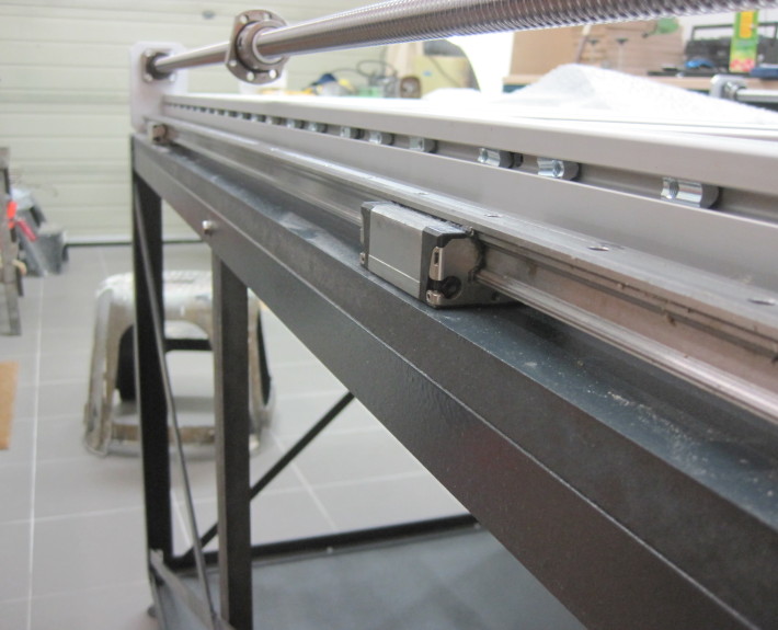
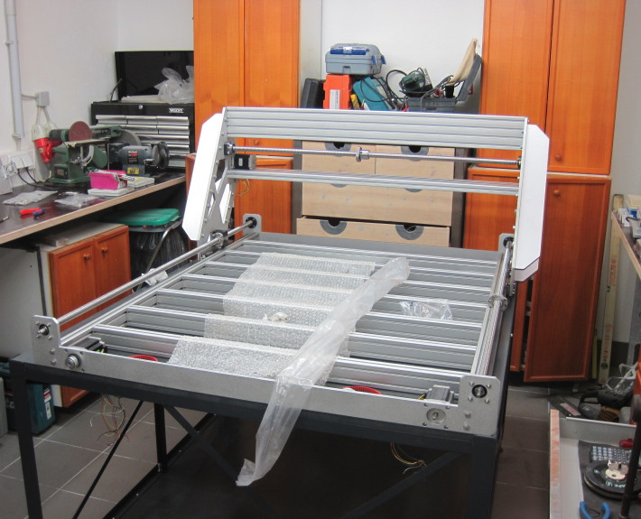
Well… I remember this as a nightmare. I bought those flip-in-flip-out groove washers which can be handy sometimes. But in this case they turned out as the most annoying little bastards I have ever seen. I had to align them before I bolted the linear rail – so screwing 1 screw… 2 screws… 13 screws … aaaaaand *blip* one bastard just decided to turn asideto take a nap… so all screws off again and position the bastard again – same game again. This took me a couple of tries – on both sides. However I did not tighten the screws at this point. All screws from the rails were just tightened so far that they wont come loose.
Looks good huh? Everything out of angle and loose of course.
Brace yourselves – many hours of alignment and head-scratching are coming!
I didn´t expect that the alignment would be so extensive… however this very important, and must be performed with a lot of patience.
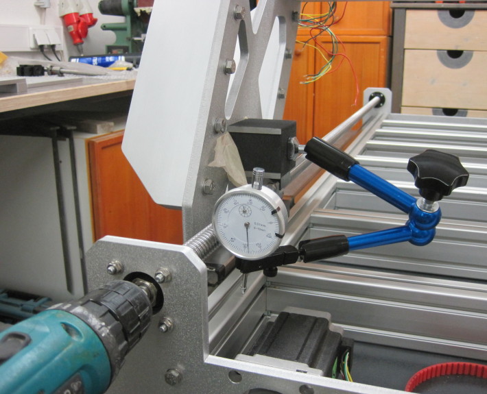
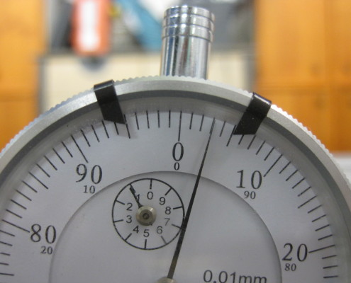
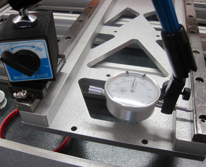
To check whether the rails are placed 100% parallel to the extrusion, I used a dial gauge. I knew, that the extrusions arn´t a good reference either, because the can be bent a little bit. Nevertheless it seemed to be the most reliable option I had available.
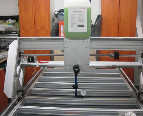
…for testing the defelection of the gantry : 10kg (100N) load bent down the entire gantry construction 0,03mm down. very acceptable!
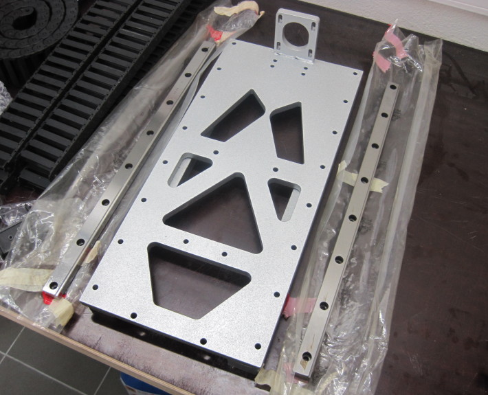
now it´s time for the z-axis! finally! I have unwrapped the THK linear rails for the first time in this picture… and I was not dissappointed. They are maybe a little bit too overpowered (a little bit too fancy-pancy either)
the linear rails can easily carry loads up to 30kN. perfect parallelism is very very (did I say very so far?) very important! Otherwise the rails could wear out quickly, as they could tense against each other rail. The best option to ensure this was by using the dial gauge again. This time I put it on one bearing block and slided it along the rail.
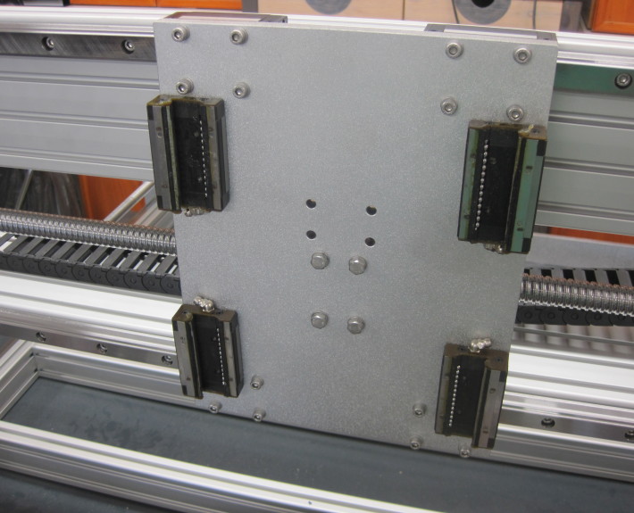
As you may have already noticed – ripper has a moving along z-spindle, which means that it has to carry its own weight when moving up and down. This method seemed the most logical to me, as the z-spindle-plate is already quite long – so why not use this length to host the screw? I also remember that I lost one of the runner-balls when sliding in the entire axis. Took me a lot of time to find the tiny steel ball again in all the dirt on the floor… and these balls are very bouncy (they are hardened) – so I found it on the other side of the room after 2 hours of searching.
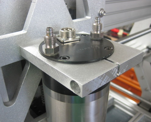
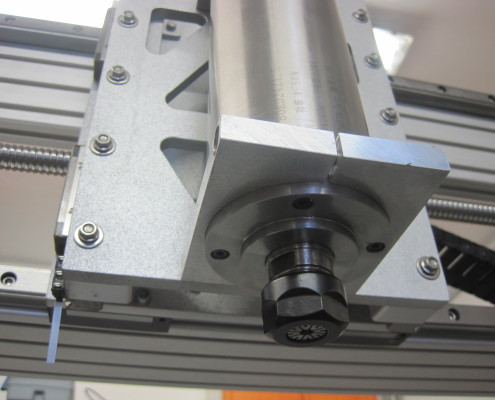
Sadly the supplier of the spindle mounts deliverd slightly different mounts, than I planed in my CAD design, and the bores were about 3 mm too far apart.
I solved this problem by clamping a 5mm round rasp into my drill, and raping the bore. This method turned out quite effective…after around 45 minutes later. yeah -_-
I havn´t made any pictures of fiddling the z-spindle between the z-spindle-plate and the y-z-connection plate.
The only step which was tricky was getting the screws into the bearing blocks. I would recommend placing the screws before everything gets too close.
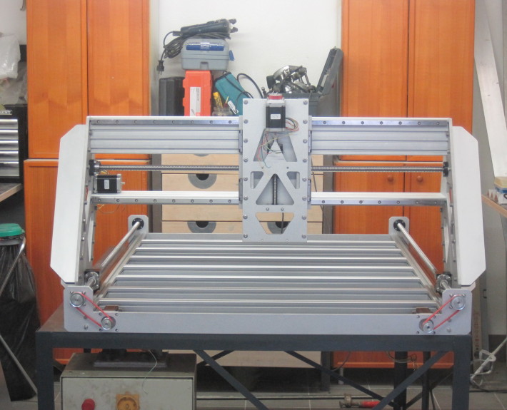
This is it! The mechanical assembly is almost done up the here! However this pile of metal in the picture above is really just a pile of metal without its steering.
